Tag Archives: electronics

Sound Skulptor MP73 – Build

Hi there!

For those who haven’t been following so far, I’ve been building some equipment for a high-quality DIY home studio for an album I’m working on for Lee Safar.

This post is about the second of two microphone preamplifier builds.  The first one ( in an earlier post ) was about the ClassicAPI VP26 ( which has a classic old 70s thick API tone), and this one, is about the Sound Skulptor MP73 ( a Neve 1290-style preamp with a warm gooey character ).

The package arrived from Sound Skulptor, so I proceeded to unwrap it:

Here is the top and bottom of the included PCB:

I started to populate the board with the diodes first, as per the excellent included instructions:

After this point however I deviate a little from the provided instructions cause I felt I had a better construction order, however, next came the resistors:

Next came the ceramic caps:

Then the film capacitors:

Then the tantalum capacitors:

Then some transistors:

Then the trimmers:

The header:

The relays:

The small electrolytic capacitors:

The terminal block connectors:

Then the main front panel switches:

Next came the potentiometers:

Then the heatsink clips were applied to the power transistor and voltage regulators:

The large electrolytic caps went in next:

The Carnhill input transformer went in next with some tricky manouvres to seat it into position:

Now the Carnhill output transformer goes in:

So then I trimmed and soldered the output transformer leads, and whacked in some IC sockets ( even though the instructions didn’t mention them, I put them in cause I have a bad track record with destroying static sensitive chips…. ):

I used the front panel, held on by the other components, to help me correctly line up the LED before soldering it, and I’m glad I did, cause now it lines up PERFECTLY.  A slight deviation from the original instructions, but easy, and accurate:

And that was it, finished!  Now I just have to do some careful cleaning of the underside of the board to remove the flux I used on the ground-plane connections ( they had to be HOT to solder properly due to the thermal dissipation…. ), but here are the shots of the final construction:

Now all that is remaining is building a power supply, casing this MP73 preamp with the VP26 one in a 1u rack case, and then, some testing.

But so far it’s looking good – not long to go now!

Catch you all soon!

manoeuvres

ClassicAPI VP26 – Build

As I’ve mentioned previously on this website, I’ve been organizing a minimal home recording studio for Lee Safar for the album I am currently producing for her.  In order to save money and also get the best possible sound we can, I’ve decided to DIY a lot of the recording equipment.

Jeff Steiger, owner of the ClassicAPI company was amazingly friendly with all of the questions I had for him when deciding to purchase this kit.  After putting in the order, about a week later, the box arrived:

Everything was beautifully packed, and the initial reaction was “wow, this is one seriously professional piece of kit….”.

Here you can see the silk-screened front panel ( which was shipped in the wrapping it’s sitting on ):

Here is a glimpse of the input transformer, output attenuator and input gain control and associated mounting hardware:

These are the main front panel switches for Mute, Phase reverse and Pad:

Here is the wrapping for the main mounting frame:

The gorgeous input transformer:

A close up of the switches including the 48V Phantom power switch:

Here is the top and bottom of the PCB that comes with the kit:

Here is the whole lot on the table:

The first thing I did was set up the workspace ( yes, I am using a Country Road magazine as a work mat – that’s how I roll – I’m not quite as well setup as when I was working at talsit‘s house! ):

Then I put in the resistors:

Followed by the diodes:

Then the latching push switches:

Then the blue Murata ceramic capacitors:

Then the large capacitors, radial and standard electrolytic went in.  The Mill-Max sockets also went in at this stage.  You’ll notice the botch job of the large 470uF capacitor with it’s horrible soldering.  A note to those building this kit – use flux!  I didn’t and it made soldering to the ground pads exceptionally difficult due to the massive thermal inertia of the exceptionally thick PCB.  I bought some flux the next day and used it to fix up that area ( which you will see in later photos ):

The input transformer went in next:

Then the output transformer ( also note the cleaner solder joint on the large axial 470uF capacitor that I cleaned up by application of flux and re-soldering ):

You can see the output attenuator now after being added:

Next the 48V Phantom power switch went in, and I started to assemble everything into the main frame, along with the front panel:

Next the knobs went on to the potentiometers:

And that was the end of the basic ClassicAPI VP26 build.  A preamp isn’t much without an amplifier now is it?  So the next part was building the gar2520 Discrete Operational Amplifier (DOA) – which performs the actual amplification task.  It’s a compatible physical layout to the original API 2520 units ( which can also be used in this kit as DOA’s ).

The first part of the gar2520 build is the pins for insertion into the Mill-Max sockets of the main VP26 board:

Next go in some resistors and capacitors:

Then the diodes:

Next are the main transistors:

Now we add some more resistors and capacitors:

And more:

And more:

And more:

And more:

And more:

And then, finally, the last parts go in to finish off the gar2520 DOA:

Now the DOA can be inserted into the main board:

And now it’s time for some modelling shots of the finished ( but untested ) product….

And now for some close-ups:

And there you have it.  Next up, the Neve-style Sound Skulptor MP73 build.  Stay-tuned for that, and the testing of this pre.

SB4000 Bus Compressor – Build – Finished

Well, we finally did it;  talsit and I finally finished building the SB4000 compressor.

Here are some images of our handiwork.  The meticulous wiring layout is mostly due to talsit.  Firstly you can see the heat-shrink applied to all bare terminals – here the compression engage and side-chain switches, and even heat-shrink also applied to cable bundles for support:

Next you can see some of the XLR wiring at the back, which uses a star-grounding scheme, that means each pair of XLR’s ( left and right ) is returned to ground separately ( which helps reduce noise and hiss ):

Next you can see the mains switch which has been hot glue-gunned for protection to remove any possibility of direct exposure to a bare live mains voltage ( should you feel the need to stick you face inside of the box whilst it’s on…. ) and the cable-ties for strain relief and rigidity to movement and bumps – it’s all about safety:

We also made sure that for future possible tweaks, things would be tied down, but not TOO much so – hence the plastic clip is used with a cable-tie, since the cable was too thick to fit through it directly and it means easy less fiddly access later on – you can also see the ribbon cable that feeds the display here too:

Red and Blue cabling was used for a consistent colour scheme throughout – to match the blue capacitors and the red circuit board – attention to detail was important to everyone involved:

For those who bought a kit of parts from diypartssupply, you would all have the same meter.  It is marked with + and – slightly indented into the white plastic, which took us a while to find…. Noting that throughout Red is + and Blue is – we hope that these images might help some other people figure out how to wire it.  We also checked this with a diode checker ( which can verify the LED on the meter – the small tabs ) and the diode check on your multimeter can move the meter also to verify it’s polarity and orientation – which we verified before soldering:

And here it is, in all it’s finished glory – waiting only for some better and sexier pot and switch knobs, and some testing and calibration – which I’ll write about next time.  It has been switched on and neither exploded nor got hot, and the switch lights and start-up procedure seemed perfectly fine.  The voltages also check out perfectly – so hopefully that means we have a fully functional compressor!:

Sound Skulptor MP73 Preamp – Kit Arrived

As a part of working with Lee Safar on her up and coming album, I’m also helping her build a studio in her home, so that as and when ideas come to her, she can record them, completely professionally, right then and there.

In order to aid this I’ve suggested she use a Shure SM7b microphone and an Apogee Duet 2 sound card.  One of the missing parts of that chain however, is a big, classic, beefy sounding preamp.  The two types of tone I wanted to give her in particular are the smooth sound of a Neve 1073 and the forward mid-biting rock sound of an API 70’s pre.  I wanted both types of sound extremes to be recorded simultaneously each time she records, so that I’m able to blend them how I want during the production stage.

In order to give her these two sounds within a small budget, I decided to build them myself from kits.  The two kits I decided upon were the Sound Skulptor MP73 and the ClassicAPI VP26 with a gar2520 discrete opamp.

Today the MP73 arrived.  It was beautifully packaged, and didn’t take very long at all to ship to Australia.  I’m very impressed with every facet of the kit, from how thorough it is ( ALL nuts and bolts, the front faceplate and even the pot knobs are provided…. ) and I can’t WAIT to start building it.  You can see in these photos the large heavy iron transformers, which impart the warm sound of this pre:


When finished, it should look a little something like this:

SB4000 Bus Compressor – Build – Day 2

Hi there!

Today was the second day I have spent working on a build of this DIY kit: http://www.prodigy-pro.com/diy/index.php?topic=40971.0.

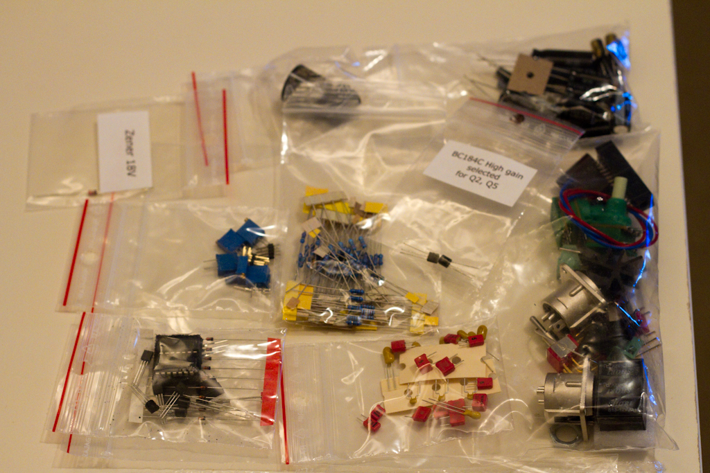
I obtained a fully inclusive parts kit from this link: http://diypartssupply.com/ which may or may not be stocked when you read this, as their stock levels vary frequently.
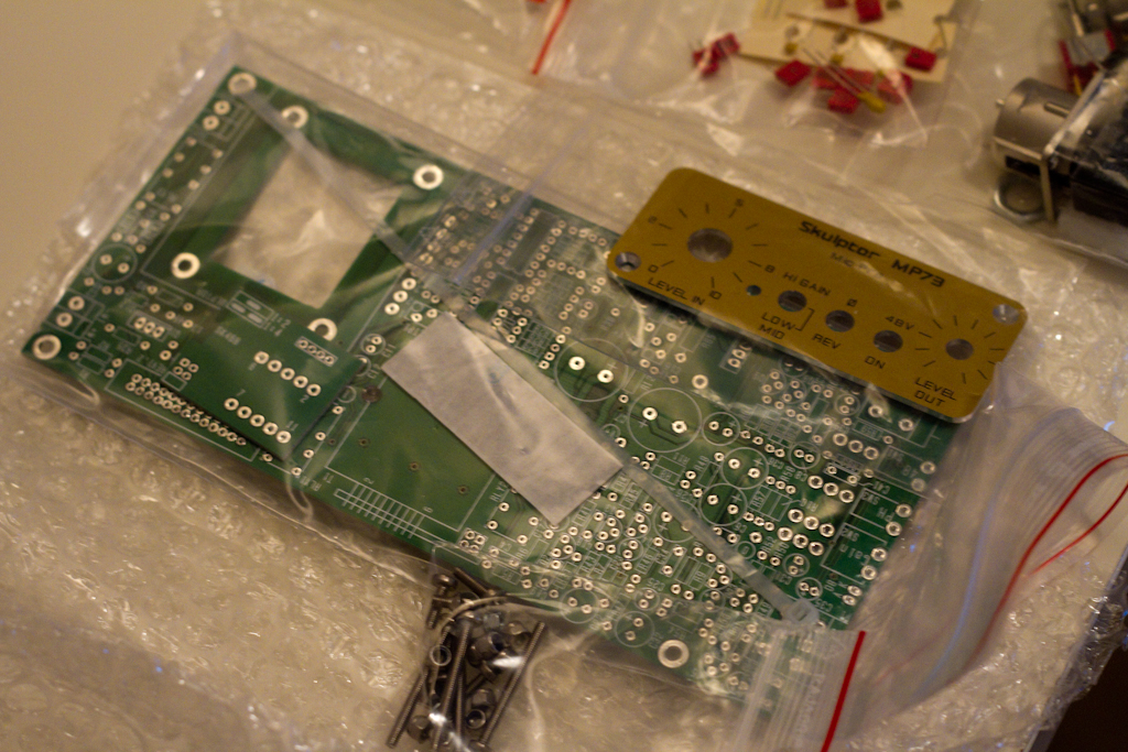
I also obtained a PCB and front panel kit from here: http://www.prodigy-pro.com/diy/index.php?topic=40755.0.

I’ll post some photos up from the start of the build yesterday, but I just wanted to share this experience with some words and images, so you can understand how much fun it was and how lucky I am to be in a position to be able to undertake something like this.

So let’s rewind again….  Huh?

OK, so, my name is Luke Emrose and I produce electronic music under the alias “evolutionary theory“.  I am a home producer based in Sydney, Australia, with a small studio and I am trying to slowly grow that studio.  I have a very detailed plan on precisely how to grow it, and what to grow it with.  My goal is, one day, to be writing electronic music soley using analog synthesizers and equipment I have build with my own hands and designs, running software that I’ve designed and programmed myself.  I am able to undertake such a giant goal for two mains reasons:  the first is that I spent much of my childhood keenly interested in electronics, building everything from some boring flashing lights, to, in high school, designing and building a fully functional 8 channel stereo audio mixing console ( Andrew, do you still have it? 😉 ), and the second is that my full time job is as a Core Software Engineer for a Visual Effects company specializing in Hollywood blockbusters.

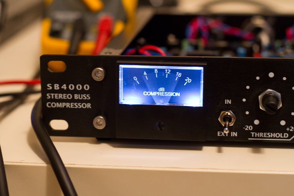
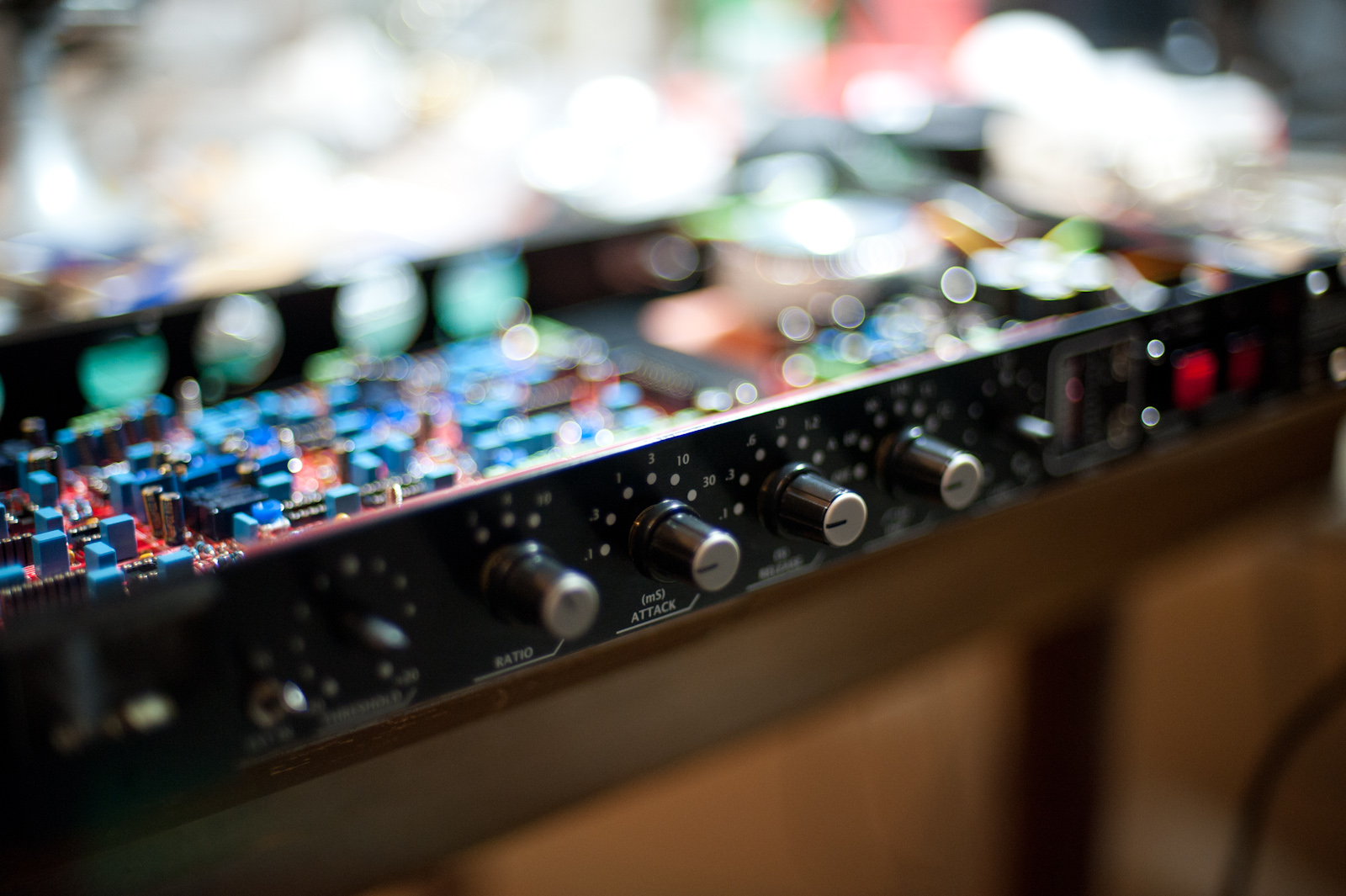
Part of my current set of after-hours tasks is producing an entire album of material for vocalist and general legend Lee Safar.  To try and keep costs down, initially we’ll be mixing and mastering the first few album tracks at a professional studio facility, but in the background I am figuring out how to absorb as much of that work back here at my home studio as possible.  One piece of equipment that I knew I had to have is the Solid State Logic 4000 G-series Bus Compressor, which inspired the Gyraf DIY GSSL project: http://www.gyraf.dk/gy_pd/ssl/ssl.htm.  The SB4000 kit that I’m discussing here was derived from the Gyraf GSSL and contains a number of extremely interesting improvements.  It took a long time for me to settle on this particular kit, but it was a combination of cost effectiveness, the quality of the kit, the copious amounts of positive feedback on the Prodigy-Pro forums about the kit, and a bunch of my own research that led me to the decision.

To build the kit I needed some help.  It’s been quite some years since I’ve laid eyes a soldering iron, let alone used one….  So, being lucky enough to go to work every day surrounded by some of the most intelligent and resourceful people I’ve ever met, meant that a close friend of mine, Talsit De Cod, could put up his hand and then his house for two days, to turn it into a batcave of circuit building ( his wife was very understanding about the mess we made, thanks for that 😉 xxx )….

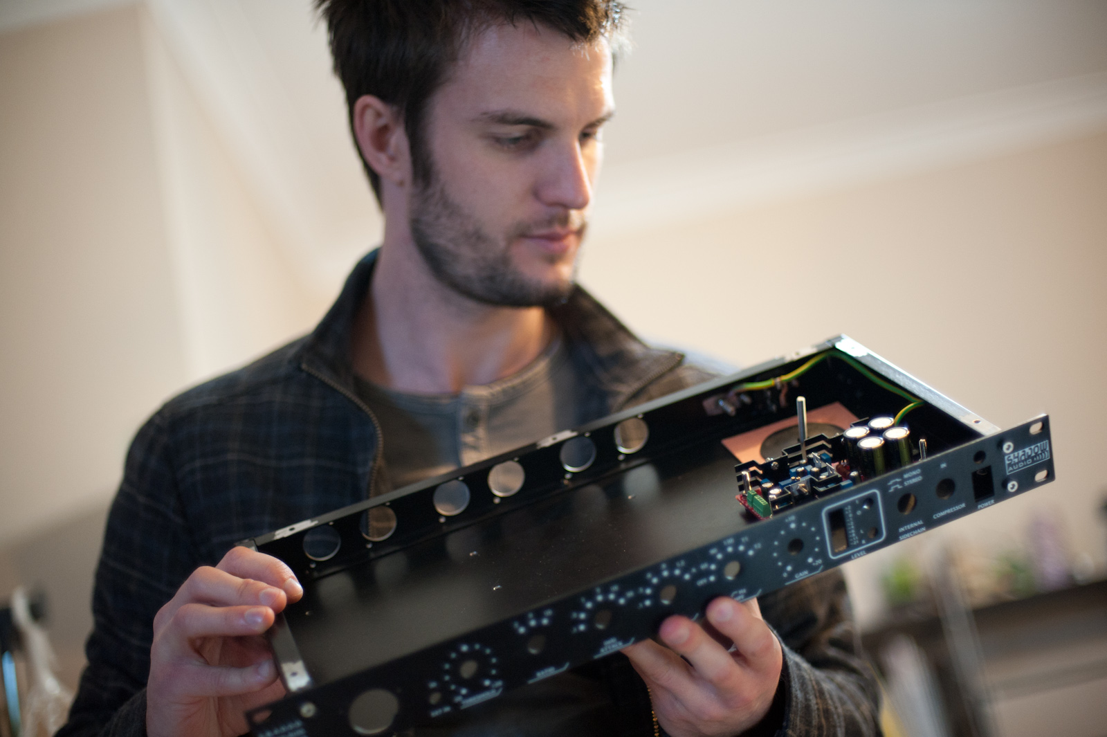
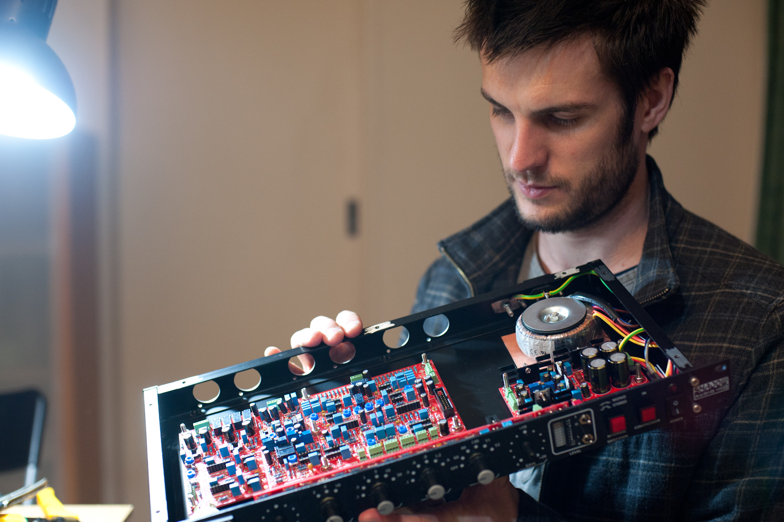
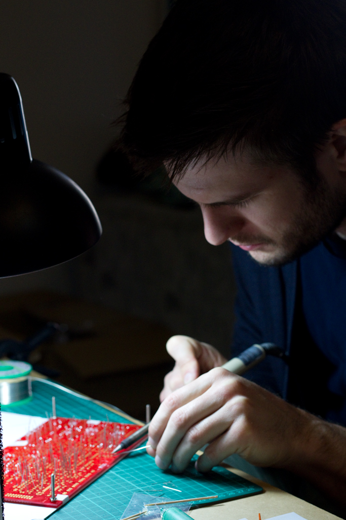
So here we are, on day 2 of the build, each working away soldering at the main SB4000 audio board ( the first image is me, the second is Talsit ):

So here is the main audio board populated with resistors and diodes:

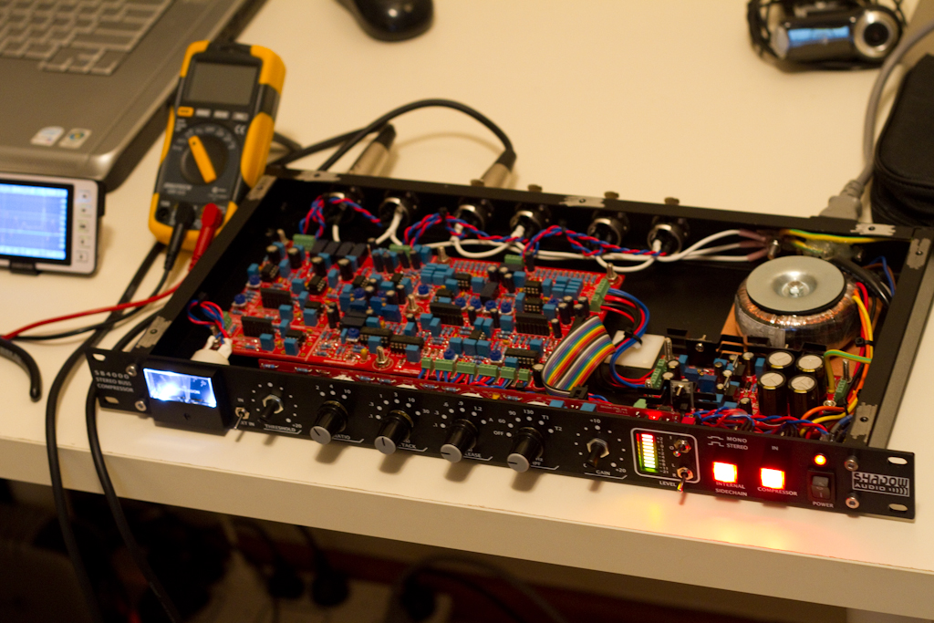
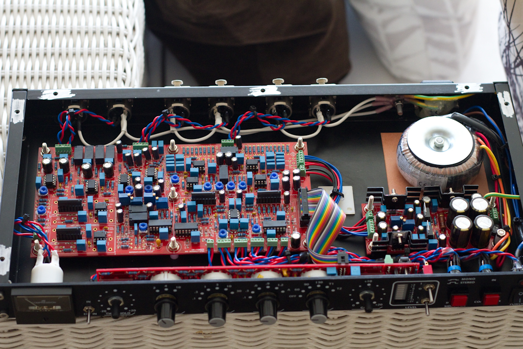
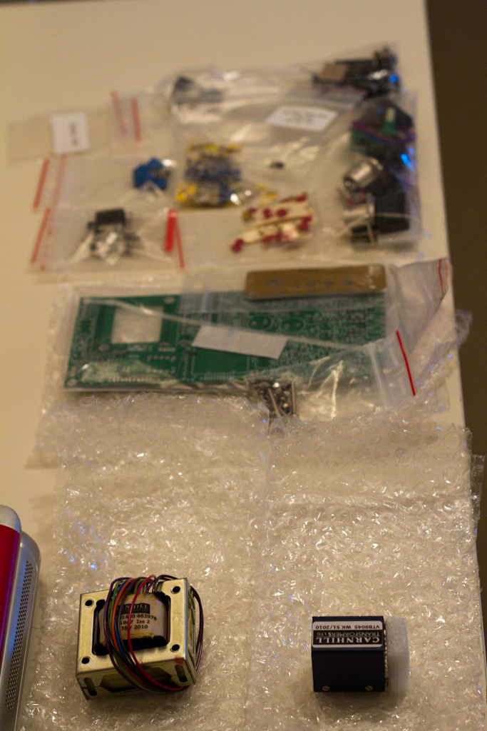
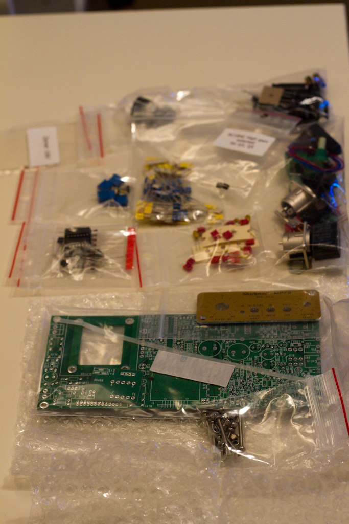
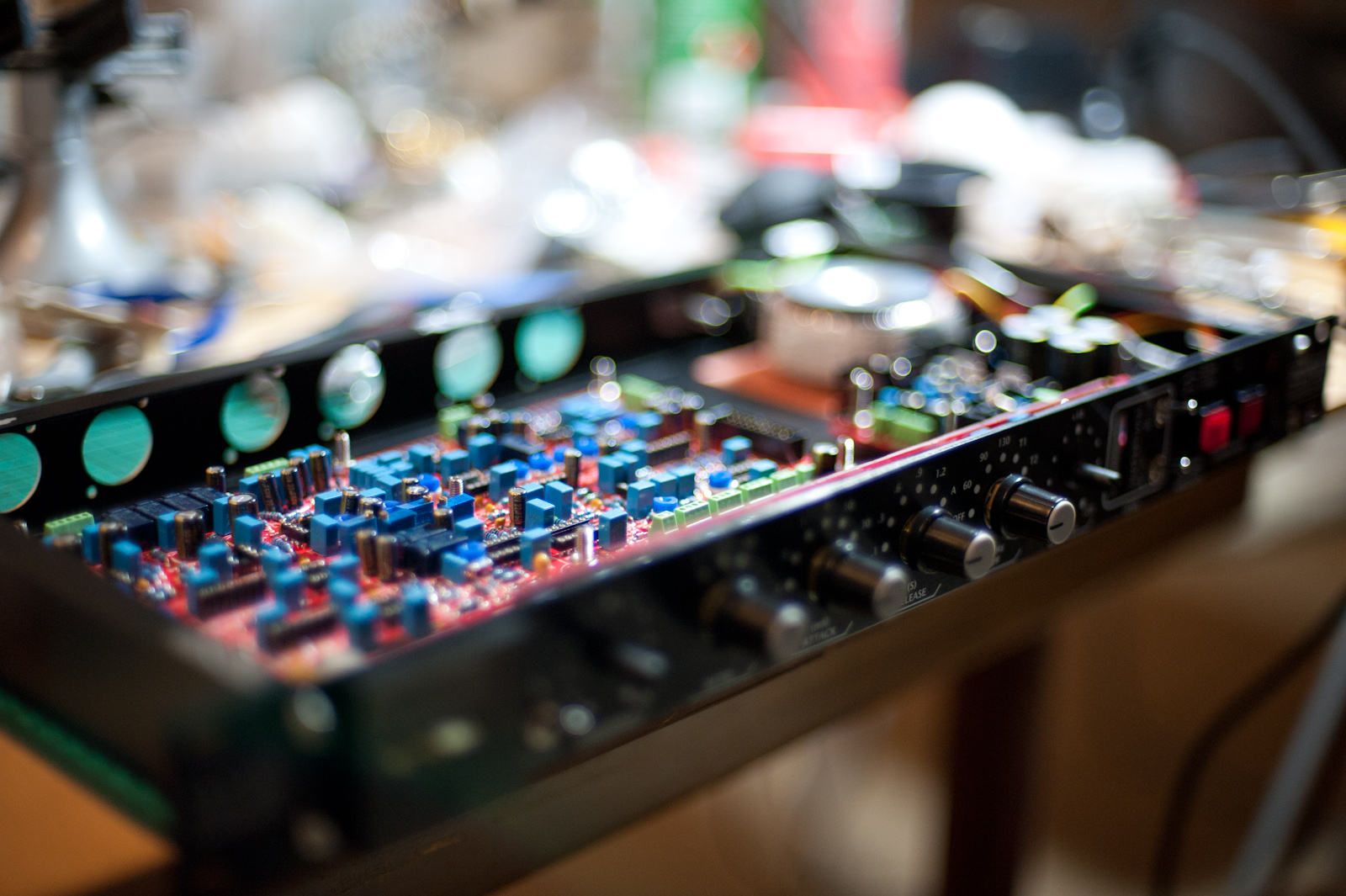
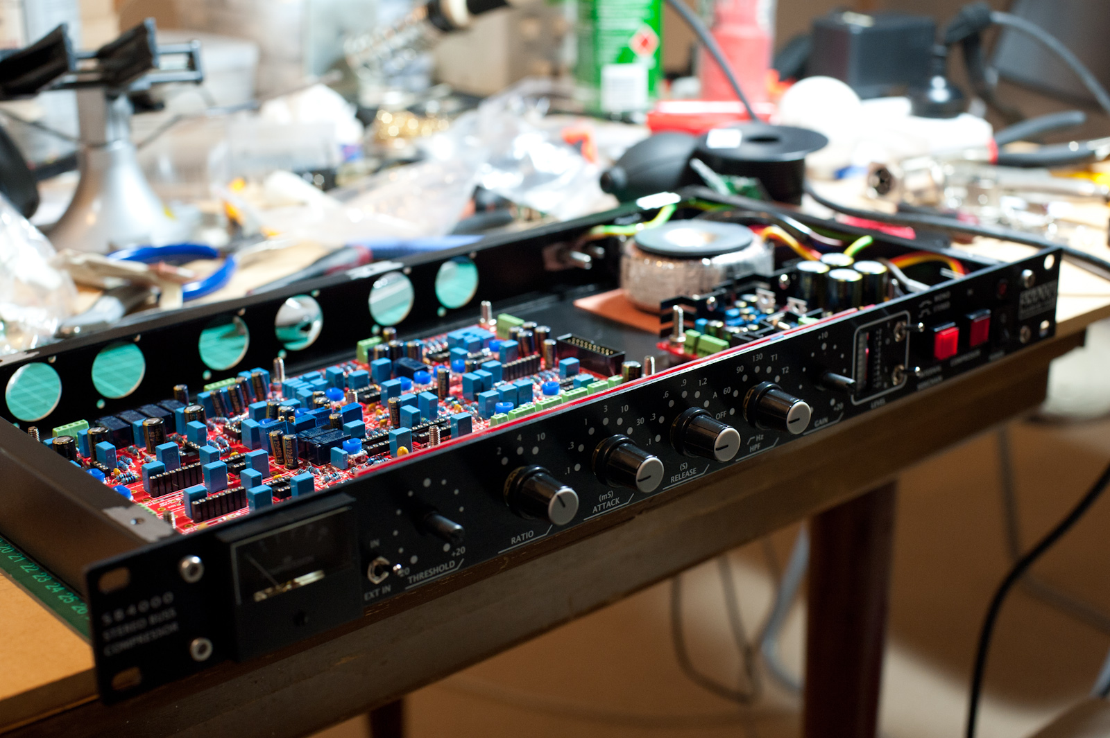
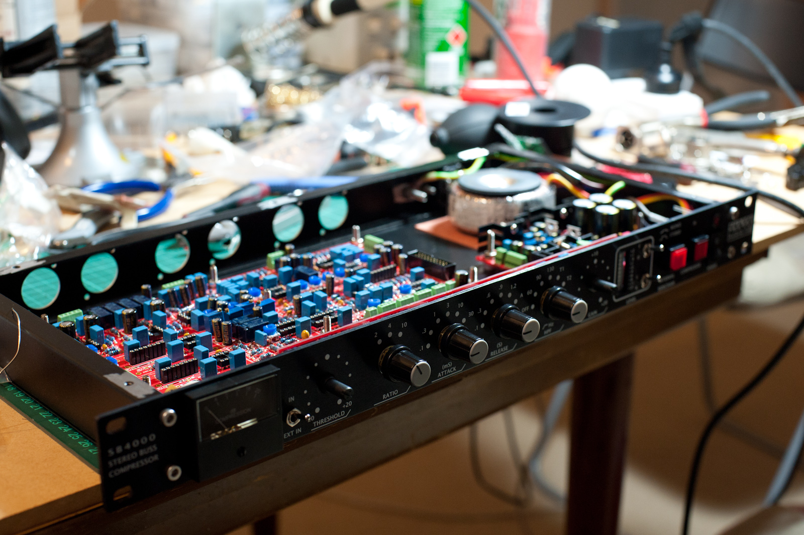
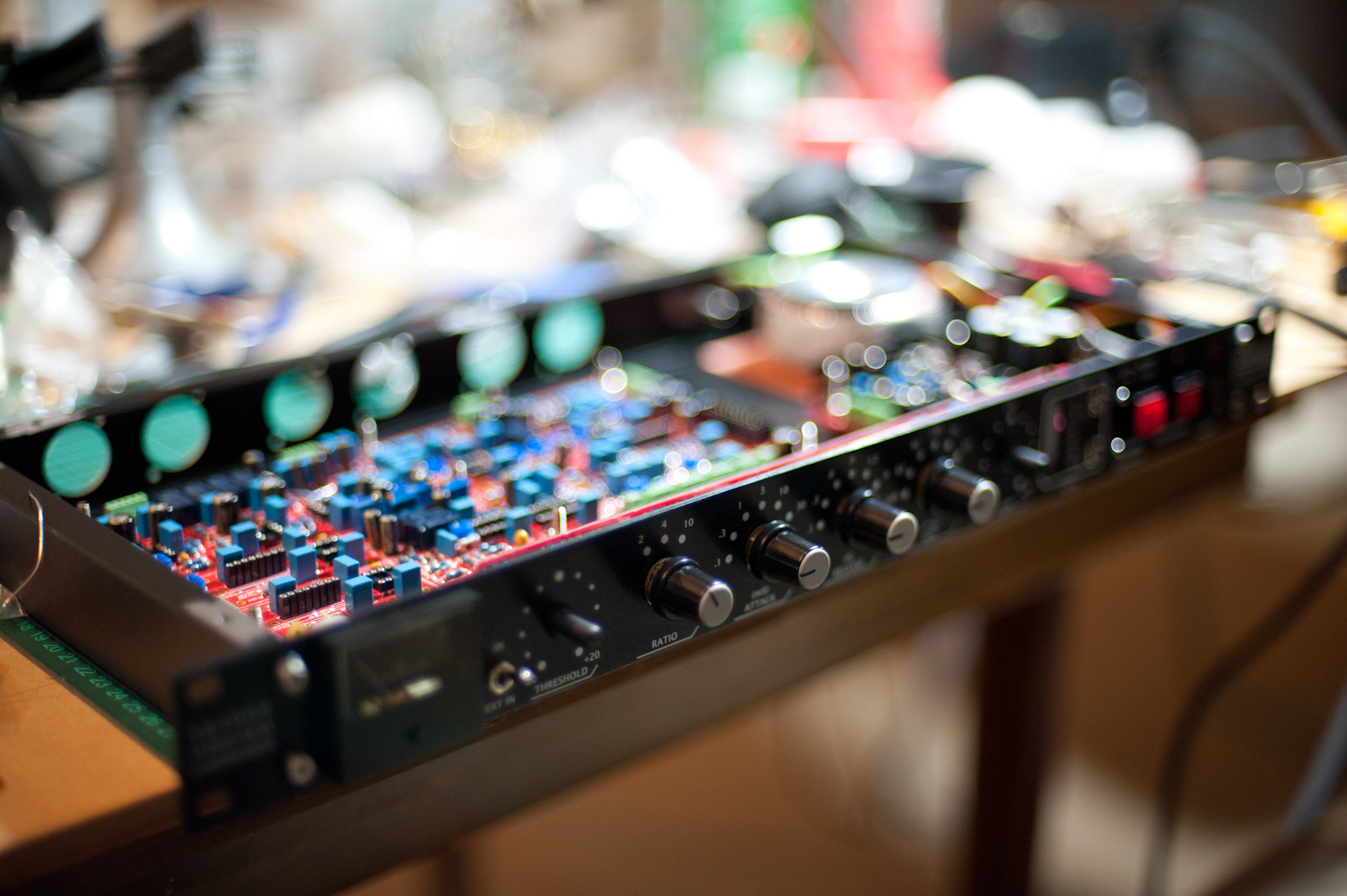
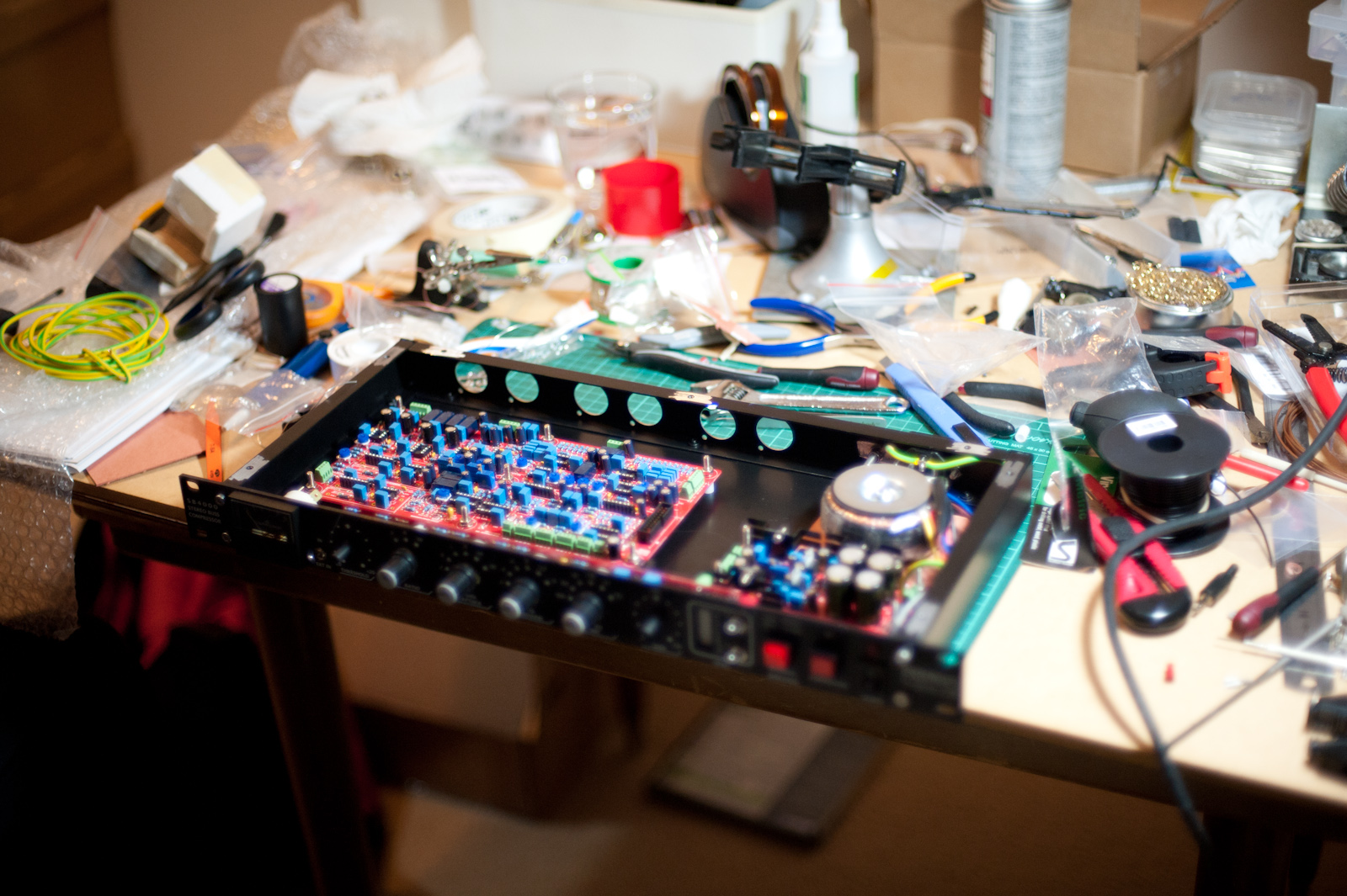
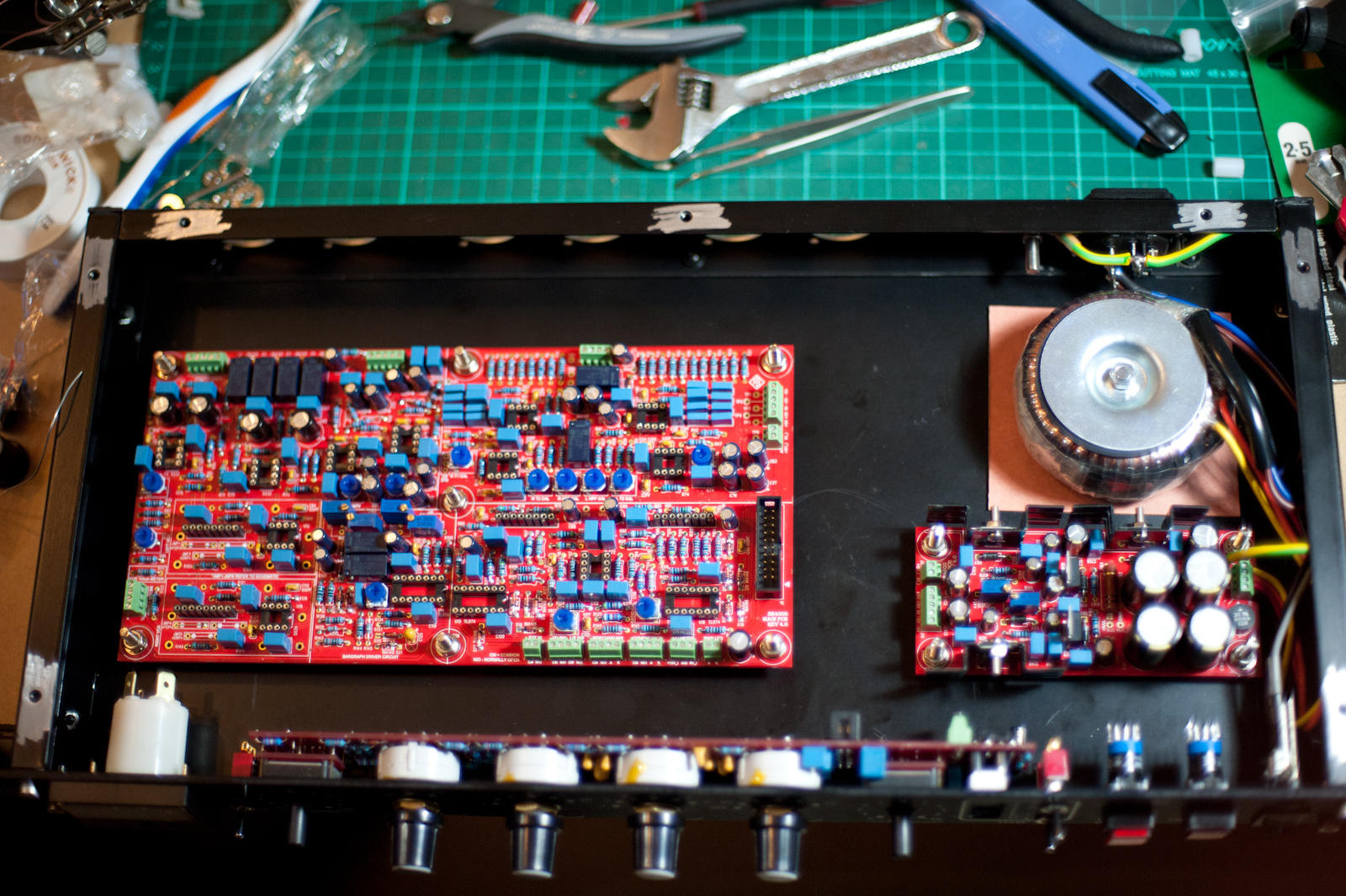
Here is a wide shot showing the mess we made of a table, the main audio board ( left ) plus the control board ( that houses the rotary dials and knobs that the user uses to interact with the compressor ), middle, and the power supply board ( which we built on day 1 ), right:

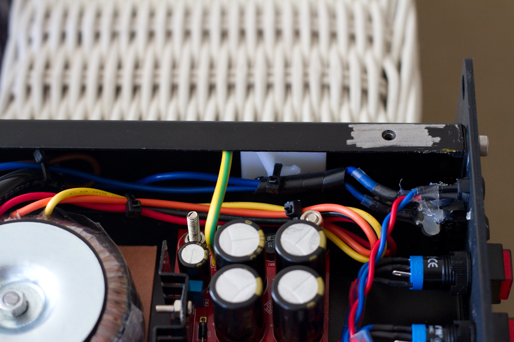
Here are a few more detailed shots of the power supply board ( which I am going to make some changes to by swapping some resistors for trimmers to more precisely control the supply rails to be +-15 and +-12V, currently it’s a little off at about 14.89V and -15.34V and similar for the 12V rails ).  I’m a sucker for accuracy ( as is Talsit…. ):

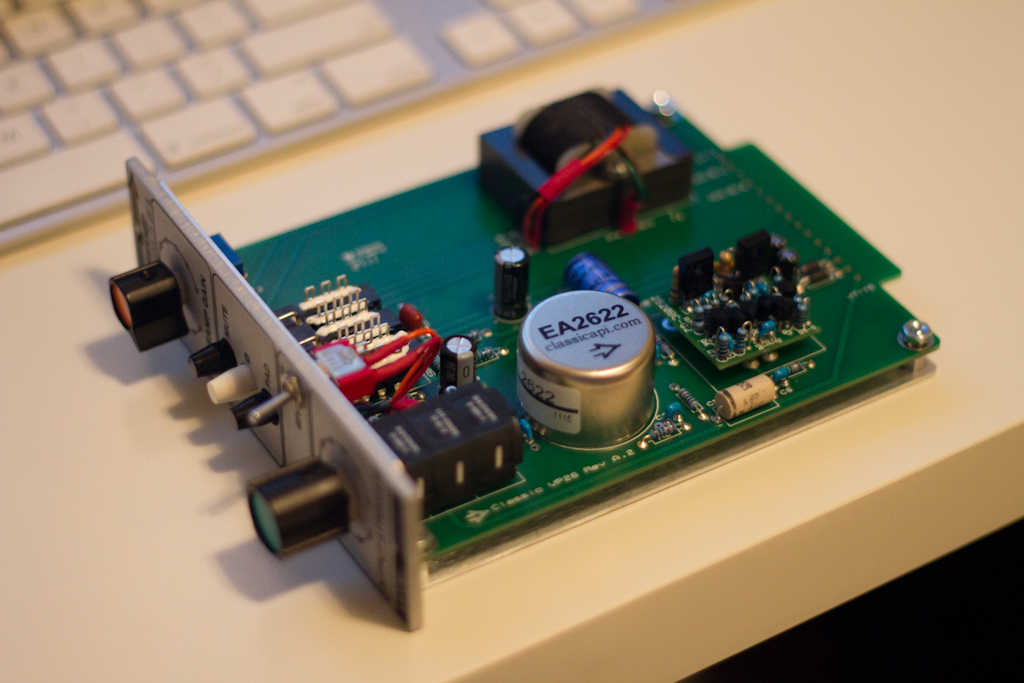
In this picture you can see the SB4000 Revision 4 PCB resistor hack ( the diagonal resistors to the left middle of the frame ).  If you decide to build this kit, please remember to read the build manual, which covers this in detail:

If you do not do this, the compressor in bypass mode will invert the phase of the signal.

Next we put in the ceramic capacitors ( the orange thingies 😉 ):

Then some polyester capacitors ( the blue ones ):

Soldering them all in place with great care:

After a LOT of soldering all of the polyester caps were in place, looking like a little city of awesome….

Next we put in the IC sockets ( the black bits ):

Now I know this next part might seem a little weird, but trust me, it IS necessary….

That’s right, we gave the board a wash with soapy water to clean off all of the flux we’d used during the first round of soldering ( flux is a compound that helps the solder stick to the components and board by both cleaning them quickly as a solvent and aiding in the thermal contact between the part and the PCB track and solder to bring them all together.  However, it’s very messy, highly corrosive and smells pretty horrid, so you godda get rid of it ):

Please note also that BEFORE washing with water, you need to use a flux remover solution; brushing the solder joints vigorously with a toothbrush ( to dissolve and start to remove the flux ), then use alcohol after that for a further clean, and brush again with a toothbrush or similar ( the alcohol dissolves all bad bits and cleans thoroughly ), and THEN wash in soapy water.

And of course after a good wash, you need a good blow-dry, so:

There we go, all nice and clean, ready for mounting the parts that are not sealed ( and hence can’t be washed ):

Next the relays ( dark blue ), ribbon cable connector ( black ), and screw terminals ( green ) went in:

Then the trimmers went in ( blue ):

During this whole time, the control board was being finished off too:

There were a few things we needed to solve, like how to mount the bourns potentiometers properly.  You get given a daughter board to place them on, but after much fiddling I think we are going to leave the daughter boards off and just mount them straight to the control PCB ( which might create issues with mechanical strength, but we don’t have much choice, since the supplied mounting nuts for the Bourns pots were incorrect and didn’t fit properly ( I’ll post some more images to show this shortly ):

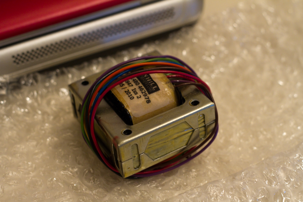
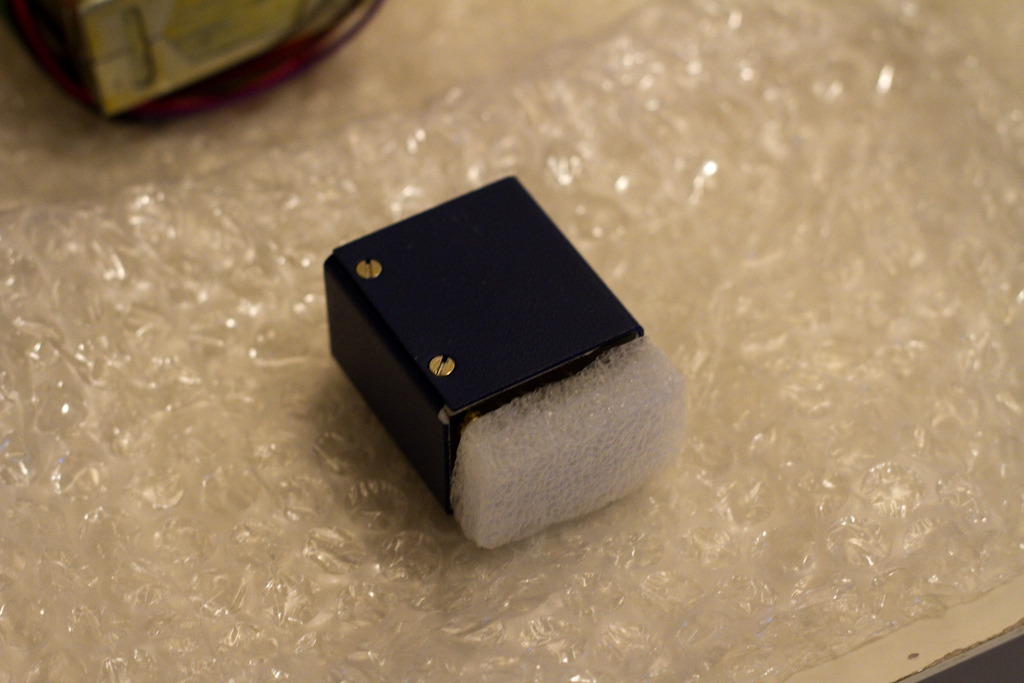
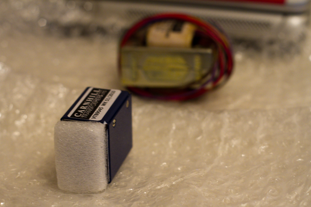
Finally we started to drill the holes to mount the different components that attach to the main case, starting with the toroidal power transformer:

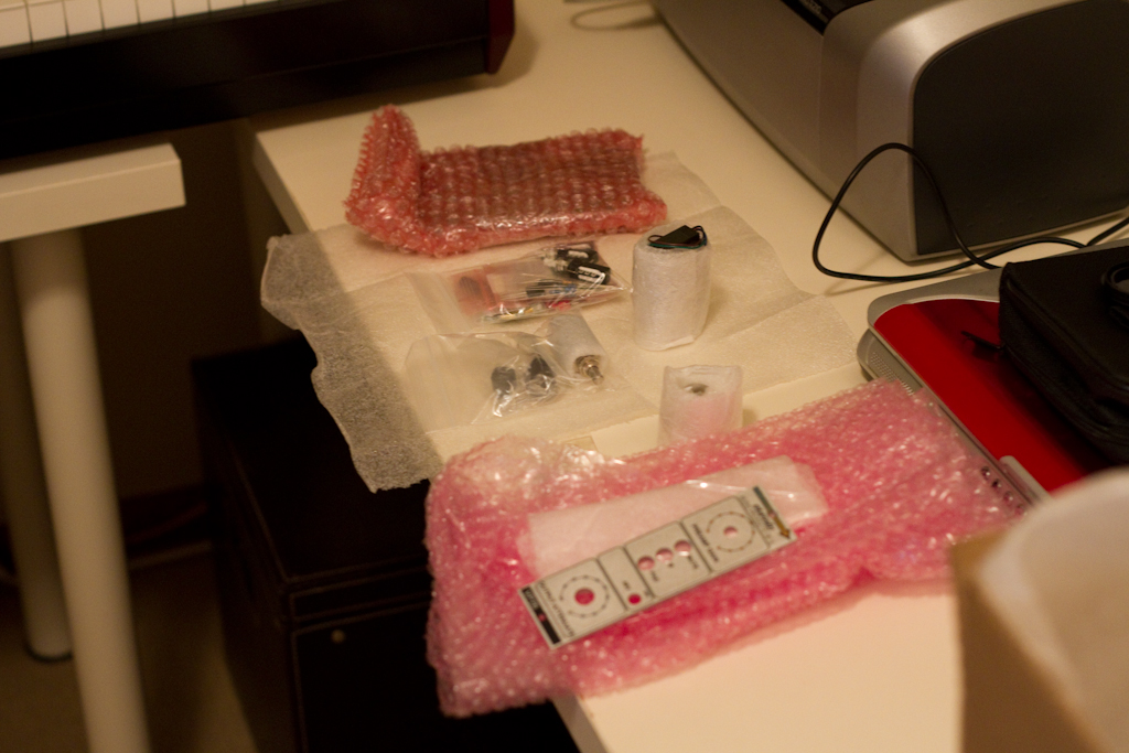
And that’s where we got up to today.  Not long to go now hopefully.  I feel it appropriate to end with a messy desk, awaiting the last portion of work: